Device tree for liteSOM/liteboard
|
<uml> title Example configuration flow\nvia device tree hide footbox box “i.MX6UL” participant "Linux kernel" as linux database "Device tree" as dtr participant GPIO as gpio participant I2C as i2c end box participant “Audio codec” as audio →> linux : start activate linux linux → dtr : read activate dtr dtr –> linux : configuration deactivate dtr linux → linux : load GPIO driver linux → gpio : configure\nGPIO pins activate gpio linux → linux : load I2C driver linux → i2c : configure I2C activate i2c linux → linux : load driver\nfor audio codec linux → i2c : configure audio i2c → audio : configure audio activate audio linux → linux : continue booting … </uml> |
Device tree is a structure used to describe hardware configuration. Each boot it is interpreted by the kernel and according to this configuration all:
are configured. In the past hardware configuration was hard coded in the source code (example), now it is a human readable file (example) compiled into a binary format FDT. If you are interested how - in details - device tree works please read Device Tree Usage and Device Tree Reference articles created by eLinux team. Generic information about device tree you can find in Booting the Linux without Open Firmware. In case when you want to develop device tree for your own hardware device tree bindings documentation will guide you how to do it. Below this section you can find few examples with configuration for litesom, liteboard and our evm. |
Device tree example with comments
Below you can find complete device tree for liteSOM.
#include "imx6ul.dtsi"

/ {
	model = "Grinn i.MX6UL liteSOM";
	compatible = "grinn,imx6ul-litesom", "fsl,imx6ul";

	memory {
		reg = <0x80000000 0x20000000>;
	};
};

&iomuxc {
	pinctrl_usdhc2: usdhc2grp {
		fsl,pins = <
			MX6UL_PAD_NAND_RE_B__USDHC2_CLK	    0x10069
			MX6UL_PAD_NAND_WE_B__USDHC2_CMD	    0x17059
			MX6UL_PAD_NAND_DATA00__USDHC2_DATA0 0x17059
			MX6UL_PAD_NAND_DATA01__USDHC2_DATA1 0x17059
			MX6UL_PAD_NAND_DATA02__USDHC2_DATA2 0x17059
			MX6UL_PAD_NAND_DATA03__USDHC2_DATA3 0x17059
			MX6UL_PAD_NAND_DATA04__USDHC2_DATA4 0x17059
			MX6UL_PAD_NAND_DATA05__USDHC2_DATA5 0x17059
			MX6UL_PAD_NAND_DATA06__USDHC2_DATA6 0x17059
			MX6UL_PAD_NAND_DATA07__USDHC2_DATA7 0x17059
			MX6UL_PAD_NAND_ALE__USDHC2_RESET_B  0x17059
		>;
	};
};

&usdhc2 {
	pinctrl-names = "default";
	pinctrl-0 = <&pinctrl_usdhc2>;
	no-1-8-v;
	non-removable;
	keep-power-in-suspend;
	wakeup-source;
	bus-width = <8>;
	status = "okay";
};
#include "imx6ul.dtsi" |
Since liteSOM is using |
/ {
    model = "Grinn i.MX6UL liteSOM";
    compatible = "grinn,imx6ul-litesom", "fsl,imx6ul";

    memory {
        reg = <0x80000000 0x20000000>;
  };
};
|
Node
Node
Node |
&iomuxc {
    pinctrl_usdhc2: usdhc2grp {
        fsl,pins = <
            MX6UL_PAD_NAND_RE_B__USDHC2_CLK      0x10069
            MX6UL_PAD_NAND_WE_B__USDHC2_CMD      0x17059
            MX6UL_PAD_NAND_DATA00__USDHC2_DATA0  0x17059
            MX6UL_PAD_NAND_DATA01__USDHC2_DATA1  0x17059
            MX6UL_PAD_NAND_DATA02__USDHC2_DATA2  0x17059
            MX6UL_PAD_NAND_DATA03__USDHC2_DATA3  0x17059
            MX6UL_PAD_NAND_DATA04__USDHC2_DATA4  0x17059
            MX6UL_PAD_NAND_DATA05__USDHC2_DATA5  0x17059
            MX6UL_PAD_NAND_DATA06__USDHC2_DATA6  0x17059
            MX6UL_PAD_NAND_DATA07__USDHC2_DATA7  0x17059
            MX6UL_PAD_NAND_ALE__USDHC2_RESET_B   0x17059
        >;
    };
};

&usdhc2 {
    pinctrl-names = "default";
    pinctrl-0 = <&pinctrl_usdhc2>;
    no-1-8-v;
    non-removable;
    keep-power-in-suspend;
    wakeup-source;
    bus-width = <8>;
    status = "okay";
};
|
More details about pinmux configuration you can find in pinmux configuration section.
Please take into account that usdhc2: usdhc@02194000 {
compatible = "fsl,imx6ul-usdhc", "fsl,imx6sx-usdhc";
reg = <0x02194000 0x4000>;
interrupts = <GIC_SPI 23 IRQ_TYPE_LEVEL_HIGH>;
clocks = <&clks IMX6UL_CLK_USDHC2>,
<&clks IMX6UL_CLK_USDHC2>,
<&clks IMX6UL_CLK_USDHC2>;
clock-names = "ipg", "ahb", "per";
bus-width = <4>;
status = "disabled";
};
|
IOMUX configuration
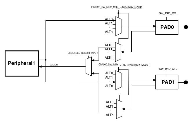
i.MX6UL has very flexible IOMUX Controller which allows each pad to share several functional blocks. Each input and output signal can be configured via dedicated multiplexers.
IOMUX Cell Block Diagram
(from i.MX 6UltraLite Applications Processor Reference Manual, Rev. 1, 04/2016)
Each pad mus be configured via following registers:
- IOMUXC_SW_MUX_CTRL_<PAD>,
- IOMUXC_SW_PAD_CTRL_<PAD>,
- <SOURCE>_SELECT_INPUT;
all of them are configured via device tree.
UART configuration for liteboard
On liteboard we are using UART1_RX pin as debug console input. Therefore in imx6ul-liteboard.dts file you can find following section.
/ {
    chosen {
        stdout-path = &uart1;
    };
};

&iomuxc {
    pinctrl_uart1: uart1grp {
        fsl,pins = <
            MX6UL_PAD_UART1_TX_DATA__UART1_DCE_TX  0x1b0b1
            MX6UL_PAD_UART1_RX_DATA__UART1_DCE_RX  0x1b0b1
        >;
    };
};

&uart1 {
    pinctrl-names = "default";
    pinctrl-0 = <&pinctrl_uart1>;
    status = "okay";
};
|
|
imx6ul-pinfunc.h contains all allowed configurations for all i.MX6UL PADS. For UART1_RX pin you can find following items.
#define MX6UL_PAD_UART1_RX_DATA__UART1_DCE_RX		0x0088 0x0314 0x0624 0 3
#define MX6UL_PAD_UART1_RX_DATA__UART1_DTE_TX		0x0088 0x0314 0x0000 0 0
#define MX6UL_PAD_UART1_RX_DATA__ENET1_RDATA03		0x0088 0x0314 0x0000 1 0
#define MX6UL_PAD_UART1_RX_DATA__I2C3_SDA		0x0088 0x0314 0x05b8 2 0
#define MX6UL_PAD_UART1_RX_DATA__CSI_DATA03		0x0088 0x0314 0x04c8 3 1
#define MX6UL_PAD_UART1_RX_DATA__GPT1_CLK		0x0088 0x0314 0x0594 4 0
#define MX6UL_PAD_UART1_RX_DATA__GPIO1_IO17		0x0088 0x0314 0x0000 5 0
#define MX6UL_PAD_UART1_RX_DATA__SPDIF_IN		0x0088 0x0314 0x0618 8 1
In the liteboard device tree we are using it as
#define MX6UL_PAD_UART1_RX_DATA__UART1_DCE_RX 0x0088 0x0314 0x0624 0 3
As described in fsl,imx-pinctrl.txt documentation each value means:
- 0x0088 - address of
IOMUXC_SW_MUX_CTL_PAD_UART1_RX_DATAregister, - 0x0314 - address of
IOMUXC_SW_PAD_CTL_PAD_UART1_RX_DATAregister, - 0x0624 - address of
IOMUXC_UART1_RX_DATA_SELECT_INPUTregister, - 0 -
IOMUXC_SW_MUX_CTL_PAD_UART1_RX_DATAregister value, - 3 -
IOMUXC_UART1_RX_DATA_SELECT_INPUTregister value.
As you can see IOMUXC_SW_PAD_CTL_PAD_UART1_RX_DATA register is not configured via MX6UL_PAD_UART1_RX_DATA__UART1_DCE_RX define. Value for this register is configured directly in device tree file.
&iomuxc {
    pinctrl_uart1: uart1grp {
        fsl,pins = <
            MX6UL_PAD_UART1_TX_DATA__UART1_DCE_TX  0x1b0b1
            MX6UL_PAD_UART1_RX_DATA__UART1_DCE_RX  0x1b0b1
        >;
    };
};
With this solution you can configure parameters like hysteresis, pull-up, pull-down, etc. directly in your device tree.
Instead of magic number 0x1b0b1 you can use defines from fsl,imx6ul-pinctrl.txt file.
Available device tree files
|
<uml> object “imx6ul.dtsi” as imx6ul object “imx6ul-litesom.dtsi” as litesom object “imx6ul-liteboard.dtsi” as liteboard object “liteSOM based project” as custom1 object “liteboard based project” as custom2 imx6ul <|– litesom litesom <|– custom1 litesom <|– liteboard liteboard <|– custom2 </uml> |
Linux contains two files:
If you need more device tree customizations you can include one of the mentioned file and extend it to fit into your project configuration. |
