SPI - Serial Peripheral Interface

Example available on GitHub. Check liteboard SPI example.
SPI is a full-duplex, master - slave, synchronous serial interface used mainly used in embedded systems.
|
<uml> ditaa /————–\ /—————\
\————–/ | | | | | | | | /---------------\
| | | | | SPI slave 2 |
| | | | | |
| | | \------>+ SCLK |
| | \-------->+ MOSI |
| \-----------+ MISO |
\------------>+ SS |
| cYEL |
\---------------/
</uml> |
Interface
SPI configurationTo configure SPI interface following parameters must be defined:
|
liteSOM and SPI
|
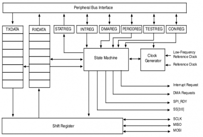
ECSPI block diagram (source: i.MX 6UltraLite Applications Processor Reference Manual) |
Each
Key features of the
|
Device Tree
ecspi1: ecspi@02008000 {
  #address-cells = <1>;
  #size-cells = <0>;
  compatible = "fsl,imx6ul-ecspi", "fsl,imx51-ecspi";
  reg = <0x02008000 0x4000>;
  interrupts = <GIC_SPI 31 IRQ_TYPE_LEVEL_HIGH>;
  clocks = <&clks IMX6UL_CLK_ECSPI1>,
           <&clks IMX6UL_CLK_ECSPI1>;
  clock-names = "ipg", "per";
  status = "disabled";
};

ecspi2: ecspi@0200c000 {
  [...]
};

ecspi3: ecspi@02010000 {
  [...]
};

ecspi4: ecspi@02014000 {
  [...]
};
|
Generic configuration for all four Documentation for all SPI related items configured in this file you can find in fsl-imx-cspi.txt file in the kernel documentation. |
&iomuxc {
  pinctrl_ecspi1: ecspi1grp {
    fsl,pins = <
      MX6UL_PAD_CSI_DATA04__ECSPI1_SCLK   0x1b0b0
      MX6UL_PAD_CSI_DATA05__GPIO4_IO26    0x1b0b0
      MX6UL_PAD_CSI_DATA06__ECSPI1_MOSI   0x1b0b0
      MX6UL_PAD_CSI_DATA07__ECSPI1_MISO   0x1b0b0
    >;
  };
};
|
SPI @ liteboard pinout To enable SPI on liteboard we have to configure IOMUX Controller to enable SPI pins for this board:
|
&ecspi1 {
  pinctrl-names = "default";
  pinctrl-0 = <&pinctrl_ecspi1>;
  cs-gpios = <&gpio4 26 GPIO_ACTIVE_LOW>;
  status = "okay";

  spidev0: spi@0 {
    compatible = "spidev";
    reg = <0>;
    spi-max-frequency = <5000000>;
  };
};
|
As a
In this example we will allow userspace application to communicate directly with SPI slave device therefore device tree contains one SPI child node
In addition
To compile -> Device Drivers
-> SPI support
-> User mode SPI device driver support
Please check spi-bus.txt file to check how to configure - via device tree - other SPI parameters. |
Test tools
Buildroot allows you build two SPI test tools:
spidev_test
Buildroot tree location
-> Target packages
  -> Debugging, profiling and benchmark
    -> spidev_test
Source code
Application source code is available here.
Loopback test
Please connect MISO and MOSI pins together and request spidev_test application to send and then receive default data package via SPI interface.
# spidev_test -D /dev/spidev0.0  -v
spi mode: 0x0
bits per word: 8
max speed: 500000 Hz (500 KHz)
TX | FF FF FF FF FF FF 40 00 00 00 00 95 FF FF FF FF FF FF FF FF FF FF FF FF FF FF FF FF FF FF F0 0D  | ......@....�..................�.
RX | FF FF FF FF FF FF 40 00 00 00 00 95 FF FF FF FF FF FF FF FF FF FF FF FF FF FF FF FF FF FF F0 0D  | ......@....�..................�.
Other options
Please check application help to see available options.
Usage: spidev_test [-DsbdlHOLC3]
  -D --device   device to use (default /dev/spidev1.1)
  -s --speed    max speed (Hz)
  -d --delay    delay (usec)
  -b --bpw      bits per word
  -i --input    input data from a file (e.g. "test.bin")
  -o --output   output data to a file (e.g. "results.bin")
  -l --loop     loopback
  -H --cpha     clock phase
  -O --cpol     clock polarity
  -L --lsb      least significant bit first
  -C --cs-high  chip select active high
  -3 --3wire    SI/SO signals shared
  -v --verbose  Verbose (show tx buffer)
  -p            Send data (e.g. "1234\xde\xad")
  -N --no-cs    no chip select
  -R --ready    slave pulls low to pause
  -2 --dual     dual transfer
  -4 --quad     quad transfer
spi-tools
Buildroot tree location
-> Target packages
  -> Hardware handling
    -> spi-tools
Source code
See spi-tools on GitHub.
spi-config
This application can be used to read/set current spidev configuration.
Read current SPI configuration
# spi-config -q -d /dev/spidev0.0
/dev/spidev0.0: mode=0, lsb=0, bits=8, speed=5000000
Set SPI configuration
To configure SPI to use mode = 2 (CPOL=1, CPAH=0) please use following command.
# spi-config -m 2 -d /dev/spidev0.0
Please read application help to see other options.
# spi-config --help
usage: spi-config options...
  options:
    -d --device=<dev>  use the given spi-dev character device.
    -q --query         print the current configuration.
    -m --mode=[0-3]    use the selected spi mode:
             0: low iddle level, sample on leading edge,
             1: low iddle level, sample on trailing edge,
             2: high iddle level, sample on leading edge,
             3: high iddle level, sample on trailing edge.
    -l --lsb={0,1}     LSB first (1) or MSB first (0).
    -b --bits=[7...]   bits per word.
    -s --speed=<int>   set the speed in Hz.
    -h --help          this screen.
    -v --version       display the version number.
spi-pipe
spi-pipe allows you to send and receive data simultaneously.
Send data via SPI interface
To send string foo via SPI interface you can use following command
# echo "foo" | spi-pipe -d /dev/spidev0.0
Read data via SPI interface
To read data received via SPI interface plse use following command
# spi-pipe -d /dev/spidev0.0 < /dev/zero | cat
More options
To see other use cases please check spi-tools README file.

