This is an old revision of the document!
liteSOM and LCD display
|
<uml w=100%> title LCD display and i.MX6UL\nblock diagram node “i.MX6UL” { package "LCD controller" {
[LCD data]
[LCD sync]
}
[Backlight]
[Touchscreen]
} [LCD data] –> RGB888 RGB888 –> [LCD panel] interface “VSYNC, HSYNC\nCLK, EN” as sync [LCD sync] –> sync sync –> [LCD panel] [Backlight] –> PWM PWM –> [LCD panel] [Touchscreen] ←- ADC ADC ←- [LCD panel] </uml> |
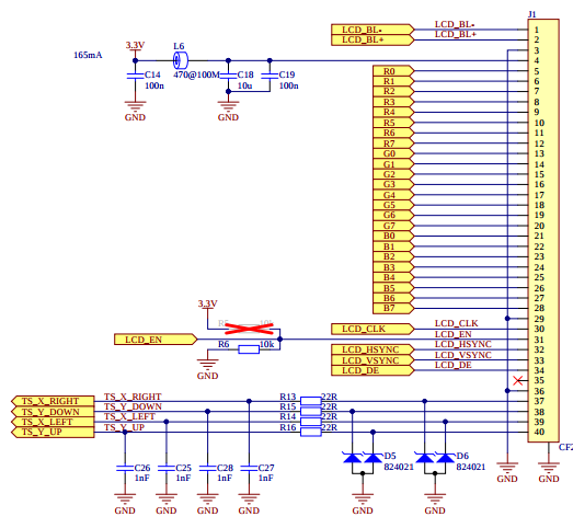
Below you can see how to configure liteboard to support lcd module. On lcd we are using RVT7.0A800480TNWR00 TFT display produced by Riverdi. Below you can find short details about this device:
|
eLCDIF - Enhanced LCD Interface
The eLCDIF can be used to drive a wide range of display devices. It supports:
- displays with resolution up to 1366 x 768,
- 8/16/18/24 bit LCD TFT displays,
- ITU-R BT.656 mode including progressive-to-interlace feature and RGB to YCbCr 4:2:2 color space conversion to support 525/60 and 625/50 operation.
|
Basic configuration for lcdif: lcdif@021c8000 {
compatible = "fsl,imx6ul-lcdif", "fsl,imx28-lcdif";
reg = <0x021c8000 0x4000>;
interrupts = <GIC_SPI 5 IRQ_TYPE_LEVEL_HIGH>;
clocks = <&clks IMX6UL_CLK_LCDIF_PIX>,
<&clks IMX6UL_CLK_LCDIF_APB>,
<&clks IMX6UL_CLK_DUMMY>;
clock-names = "pix", "axi", "disp_axi";
status = "disabled";
};
which is used by mxsfb driver.
In the mxsfb.txt file you can find documentation with information how to configure In addition please check display-timing.txt file with information how to configure display timings. |
&iomuxc {
  pinctrl_lcdif_ctrl: lcdifctrlgrp {
    fsl,pins = <
      MX6UL_PAD_LCD_CLK__LCDIF_CLK       0x79
      MX6UL_PAD_LCD_ENABLE__LCDIF_ENABLE 0x79
      MX6UL_PAD_LCD_HSYNC__LCDIF_HSYNC   0x79
      MX6UL_PAD_LCD_VSYNC__LCDIF_VSYNC   0x79
    >;
  };

  pinctrl_lcdif_dat: lcdifdatgrp {
    fsl,pins = <
      MX6UL_PAD_LCD_DATA00__LCDIF_DATA00  0x79
      MX6UL_PAD_LCD_DATA01__LCDIF_DATA01  0x79
      [...]
      MX6UL_PAD_LCD_DATA23__LCDIF_DATA23  0x79
    >;
  };
};


&lcdif {
  pinctrl-names = "default";
  pinctrl-0 = <&pinctrl_lcdif_dat
               &pinctrl_lcdif_ctrl>;
  display = <&display0>;
  status = "okay";

  display0: display {
    bits-per-pixel = <32>;
    bus-width = <24>;

    display-timings {
      native-mode = <&timing0>;
      timing0: timing0 {
        clock-frequency = <30000000>;
        hactive = <800>;
        vactive = <480>;
        hfront-porch = <210>;
        hsync-len = <2>;
        hback-porch = <46>;
        vfront-porch = <22>;
        vsync-len = <2>;
        vback-porch = <23>;
        hsync-active = <1>;
        vsync-active = <1>;
        de-active = <1>;
        pixelclk-active = <0>;
      };
    };
  };
};
|
In our case we have to connect
In addition
Nodes Here you can read more about
IOMUX Conctroller configuration via device tree.
Node To help you to understand timing configuration please check following image. +----------+---------------------------------+----------+-------+ | | ↑ | | | | | | 46 lines | | | | | ↓ | | | +----------###################################----------+-------+ | # ↑ # | | | 46 # | # 210 | 2 | | pixels # | 800 pixels # pixels | pixels| |<-------->#<-------+----------------------->#<-------->|<----->| | # | # | | | # | 480 pixels # | | | # ↓ # | | +----------###################################----------+-------+ | | ↑ | | | | | | 22 lines | | | | | ↓ | | | +----------+---------------------------------+----------+-------+ | | ↑ | | | | | | 2 lines | | | | | ↓ | | | +----------+---------------------------------+----------+-------+ (based on: Documentation/devicetree/bindings/video/display-timing.txt)
In addition to device tree please remember to enable -> Device Drivers
-> Graphics support
-> Frame buffer Devices
-> MXS LCD framebuffer support
|
TSC - Touch Screen Controller
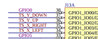
i.MX6UL touchscreen controller can be used with 4-wire and 5-wire resistive touchscreens. Built-in A/D converter has 8-bit/10-bit/12-bit resolution. Parameters like pre-charge or de-glitch are fully configurable.
From software point of view TSC is controlled via imx6ul-tsc driver (see imx6ul_tsc.c). In imx6ul_tsc.txt
file you can find information how to configure device tree for this peripheral.
&iomuxc {
  pinctrl_tsc: tscgrp {
    fsl,pins = <
      MX6UL_PAD_GPIO1_IO01__GPIO1_IO01  0xb0
      MX6UL_PAD_GPIO1_IO02__GPIO1_IO02  0xb0
      MX6UL_PAD_GPIO1_IO03__GPIO1_IO03  0xb0
      MX6UL_PAD_GPIO1_IO04__GPIO1_IO04  0xb0
    >;
  };
};

&tsc {
  pinctrl-names = "default";
  pinctrl-0 = <&pinctrl_tsc>;
  status = "okay";
  xnur-gpio = <&gpio1 4 GPIO_ACTIVE_LOW>;
  measure_delay_time = <0xffff>;
  pre_charge_time = <0xfff>;
};
|
Node
To compile imx6ul_tsc.c driver please select -> Device Drivers
-> Input device support
-> Generic input layer (needed for keyboard, mouse, ...)
-> Touchscreens
-> Freescale i.MX6UL touchscreen controller
|
Backlight
|
<uml> package “liteboard” { [PWM backlight driver] → [PWM] } package “Display” { [PWM] → [Backlight] } </uml> / {
backlight {
compatible = "pwm-backlight";
pwms = <&pwm2 0 5000000>;
brightness-levels = <0 4 8 16 32 64 128 255>;
default-brightness-level = <6>;
status = "okay";
};
};
&iomuxc {
pinctrl_pwm2: pwm2 {
fsl,pins = <
MX6UL_PAD_GPIO1_IO09__PWM2_OUT 0x110b0
>;
};
};
&pwm2 {
pinctrl-names = "default";
pinctrl-0 = <&pinctrl_pwm2>;
status = "okay";
clocks = <&clks IMX6UL_CLK_PWM2>,
<&clks IMX6UL_CLK_PWM2>;
};
|
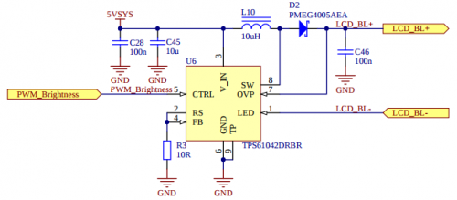
On liteboard you can find dedicated LCD backlight boot converter (see TPS61042) controlled by litesom via
Backlight can be controlled directly via
Node Backlight configured as presented here will:
Node
Node |
 Show how to test this setup.


